servostik

ArcadeJoystick
with 4-way to 8-way powered restrictor switching
Motor-driven restrictor plate switches between 4 and 8 way in less than
a second
USB Servo Control board drives two joystick servos.
Can also be switched in a standalone setup (no PC) using two buttons or
a toggle switch
Multiple control boards can be used on one PC for 4 or more players
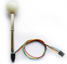
Optional RGB Illuminated handle available.
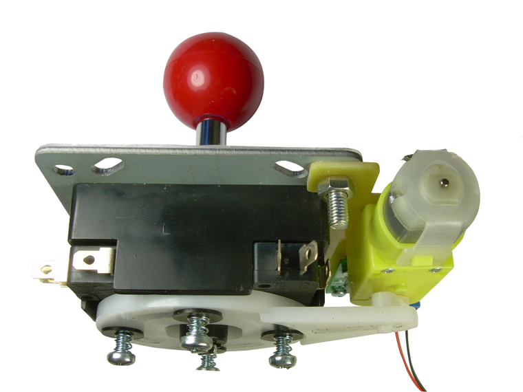
Note: Above pictures show 2 x joystick mounting screws which are not
included. We have separate mounting kits available for wood panels.

- At last! Full mechanical 4-8
way restriction with powered switching.
- Separate control board plugs
into a USB port and controls the servos on two joysticks.
- Comprehensive software
support including test utility and a special utility which can be
command-line or GUI driven.
- Integrated into the Ultimarc
DLL which provides API calls to perform switching, for front-end
developers.
- No separate power required.
Takes power from USB port
- Hardware mode also allows
switching using two buttons or a toggle switch.
- Switches are connected in the same way as a standard joystick, to
a suitable interface such as an I-PAC.
Installation
The ServoStik consists of three parts:
Base Joystick:
This is installed and wired to an interface in the same way as any
standard arcade stick.
Mounting method depends on panel design, material and thickness.
Our blind-hole mounting kits can be used on wood panels of thickness
5/8 in or greater.
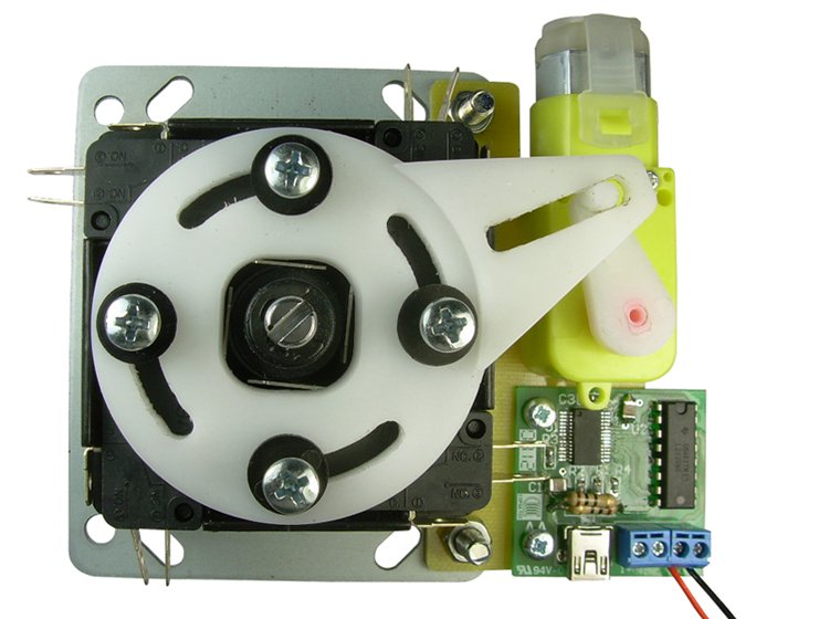
Motor:
The motor baseplate mounts using two of the same mounting screws as the
base joystick. NOTE; The two screws shown in the pictures above, which
secure the motor baseplate to the joystick are NOT INCLUDED as these
are part of the joystick mounting hardware.
Control Board
The control board can be mounted to the motor baseplate of
one of the
two sticks using supplied mounting hardware. Wires from each motor need
to be connected to the screw terminals.
One control board drives two motors.
A four-player panel will require two control boards.
Software
Support
Test Application
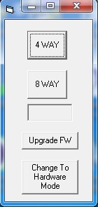
This simple application can
be downloaded
here.
It simply has two GUI buttons for switching to 4-way or 8-way.
All detected control boards (and therefore pairs of sticks) are
switched.
The app is also used for PERMANENTLY switching to hardware mode (see
below).
JoyTray

This application can be downloaded
here:
It supports both the ServoStik and our Ultrastik 360
Running JoyTray from command
line:
JoyTray.exe
-servo [joy4way|joy8way]
(If using Ultrastik 360:
JoyTray.exe
-u360
[mouse|analog|joy8way|easyjoy8way|joy4way|djoy4way|rdjoy4way|joy2way|vjoy2way])
If you add an -exit argument the program will exit without staying
resident.
Until front-end developers add native support for the ServoStik, this
is the way to automate switching. The front-end needs to be configured
to run a command line before starting games eg:
JoyTray.exe
-servo joy8way
before all 8-way games
JoyTray.exe
-servo joy4way
before all 4-way games
JoyTray Hotkeys:
When resident: F4 switches to 4-way and F8 switches to 8-way.
You could assign I-PAC-connected controls to these keycodes.
Maybe use I-PAC shifted codes.
JoyTray GUI Mode:
Launch JoyTray.exe by itself and it will show an icon in the
tray which
can be right-clicked to show a menu. It will gray out the U360 or
ServoStik menu items based on whether you have them attached.
There is an option to run the program at startup.
Third-PartySoftware and SDK Support
As most third-party software and our SDK is cross-product, we have
placed all details on
this page.
Hardware
Mode
This special mode is used when there is no PC and you need to switch
the stick using a toggle switch or two buttons.
The control board can be placed into hardware mode using the test
application (see above). Note this change is PERMANENT.
Switching between 4 and 8 way is done using either two buttons or a
toggle switch.
To connect the buttons, cut the A plug from the USB cable and strip the
wires.
Connect the RED wire to a 5 volt source. (JAMMA power supply for
example)
Connect the BLACK wire to Ground on the power supply
Connect the Green wire to the NO contact of a pushbutton for 4 way
Connect the White wire to the NO contact of a pushbutton for 8 way
Connect the COM connections of both buttons to the black daisy-chain
wire which runs to all other controls, or to the power supply ground.
Alternatively you can use a toggle switch with the center connection to
ground and the end connections to the green and white wires.
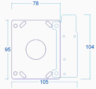
Mounting
Diagram
Click
for PDF Template
Dimensions in mm