(also see
DIY Optical Sensor Page)
Connecting the Ultimarc/STC 2-1/4 inch trackball or Ultimarc U-Trak
This is supplied with connecting cables. There is one cable per axis.
The location of the two plugs is described in the table looking from
the
top.
The GND and +5V from both plugs go to the same GND and +5V connections
on the Opti-PAC.
| Plug at "12 o'clock" position |
Plug at "9 o'clock" position |
| Black |
Red |
Yellow |
Green |
Black |
Red |
Yellow |
Green |
| GND |
+5V |
Y1 |
Y2 |
GND |
+5V |
X2 |
X1 |
Connecting a Happ trackball
The Happ trackball is supplied with a connecting cable. Cut off the
large plug mounted on one end. Strip a short length of each wire and
connect as shown in the table below. Set the jumper to "A/LO".
| Black (2 wires) |
Red (2 wires) |
Purple |
Blue |
Yellow |
Green |
| GND |
+5V |
X1 |
X2 |
Y1 |
Y2 |
There are two +5V and GND wires. These can both be connected to the
same +5V or GND connection.
The Happ trackballs have a green ground wire. This is to prevent static
buildup and can be connected to any convenient ground point.
Plug USB cable into the connector on the board and connect to the PC
USB port. The PC will auto-detect the device and install a standard
mouse driver. (Actually it installs two mouse devices)
Software
Windows
There is no need for any extra software when using Windows. The
Opti-Pac appears to Windows as two standard HID mouse devices.
Buttons.
If required connect two buttons to the button connections as marked
(left button, right button). For each button, one connection goes to
one of the two button inputs, the other goes to any connection marked
"GND". You can use your control-panel buttons which are already
connected to an I-PAC board. Just wire them to both an I-PAC input and
an Opti-Pac mouse button input.
Correcting Reverse Movement.
Depending on the orientation of the trackball the horizontal and
vertical movement may be reversed.
If the horizontal and vertical axes are reversed, swap the "X" wire
connections with the "Y" connections.
If either of the horizontal or vertical movements are backwards, swap
the X1 wire with X2 or swap Y1 with Y2 as appropriate.
Other Devices
Connecting a Suzo or Wico 2 1/4" Trackball.
The Suzo trackball (also supplied by Wico) is supplied with two plugs
which are designed to have wires pushed into the connections. A small
screwdriver is needed to do this. The pins are numbered on the plug, 1
to 4. There is one plug for vertical axis and one for horizontal.
Connect as follows:
| Vert 1 |
Vert 2 |
Vert 3 |
Vert 4 |
Horiz 1 |
Horiz 2 |
Horiz 3 |
Horiz4 |
| +5V |
Y1 |
Y2 |
GND |
+5V |
X1 |
X2 |
GND |
There are two models of Suzo trackball: Active High and Active
Low.
These are the part numbers:
29-0210: Active Hi White ball
29-0210-2: Active Hi Red ball
29-0230: Active low White ball
29-0230-1: Active low Red ball
See above for button connection and software.
Adding more devices.
Another device such as a spinner or rotary joystick can be added to
player 1 or 2.
Connect as above to the connection group marked "P1 Rotary". A spinner
uses only one axis so connect this to the X1 and X2, +5V and GND only.
A second single-axis device can be connected to Y1, Y2, +5V and GND.
The selection of which axis to be used in each game (and therefore
which control) can be made in MAME.
Connection of devices to Player 2 is identical to Port 1. The automatic
device switching described above applies to Player 2 also. Player 2
uses a second USB mouse device (although this is via the same cable as
Player 1). Current MAME versions support independent mouse devices.
Detailed Information.
Any optical wheel type sensor type device
can be connected to the Opti-Pac. In order to connect other devices
this section contains further information on the connections.
How a track ball works.
A trackball functions in exactly the same way as a mouse. Each axis has
a slotted optical wheel which is located between two sensors mounted
alongside each other. The two sensors generate pulses when the wheel is
rotated. These pulses are decoded by the software in the
microcontroller (on the Opti-Pac board or inside the mouse) to generate
horizontal or vertical movement information which is sent to the PC.
The two sensors correspond to the X1 and X2 inputs of the Opti-Pac, or
the Y1 and Y2 for vertical. On a trackball the horizontal and vertical
axes are two completely separate circuits.
A spinner is a single-axis device so simply has only one of these two
identical circuits. This means two spinners require the same number of
inputs as one trackball.
Connection Schematic.
Below is a schematic showing one Suzo Active High trackball and two
buttons connected to the Opti-Pac.
Here is some information on the function of each connection and jumper
in order to interface other controls to the board:
| X1,X2 Y1,Y2 |
Inputs from the phototransistors on the optical sensor |
| +5V |
Positive voltage supply to the optical sensor LED. Note that
all connections marked +5V are connected together on the board and any
one can be used. |
| GND |
Return from the optical sensor LED. Note all connections
marked GND are connected together on the board so any one can be used. |
| Port n Button L |
Left mouse button input. (connect other switch contact to any
GND) |
| Port n Button R |
Right mouse button input. (connect other switch contact to
any GND) |
|
|
The optical sensor connections are grouped into four control groups.
Each of the four groups can accept one trackball or two single-axis
devices such as spinner, rotary joystick etc.
There is no difference in the function of the "Trackball" groups and
"Rotary" groups. The different names are for convenience only.
The two control groups marked "P1 Trackball" and "P1 Rotary" are routed
to Mouse 1 (Player 1).
The two control groups marked "P2 Trackball" and "P2 Rotary" are routed
to Mouse 2 (Player 2)
Using Active-High devices.
Almost all optical controls are active-low, which means the outputs are
actively pulled to zero volts, or left "open", depending on the
position of the optical spoked wheel.
If your device is "Active High", it will pull the outputs to 5 volts,
or leave "open" depending on the wheel position.
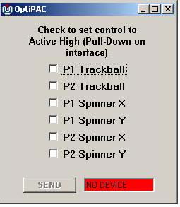
The Opti-PAC can be configured to handle Acrive-High devices using a
simple software utility. Just click on the check-boxes for the inputs
you need to be set to active-high.
 Click here
 to download this
utility. Unzip into a folder (2 files).
Troubleshooting Trackball Connection Problems.
If you have no trackball movement, try the following.
Remove one trackball optical sensor PCB from the trackball. These slide
out after removing a small round retainer with a tab.
The track side of the PCB should look like this. If it is the "special"
type for Mini-PAC it will have two extra resistors added to this side.
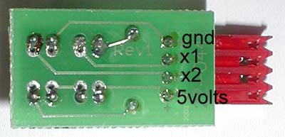
With a voltmeter check the following with the board still connected to
the Opti-PAC.
Black probe on GND, red on 5 volts. This should read 5 volts.
If this does not read 5 volts, check the wiring from the PCB locations
to the 5V and GND tags on the Opti-PAC. Use the continuity setting on
the meter, after disconnecting the Opti-PAC from the PC (ie remove
power)
Black probe on GND, red on X1
The voltage should be approx 0.5 volts. Then place an object in the
slots on the sensors on the other side of the board. The voltage should
rise to approx 4.5 volts.
Voltage stuck low: this indicates a wire problem between the PCB and
the Opti-PAC terminal, or Hi/Lo jumper not set to LO.
Voltage stuck high indicates a problem with the optical sensor or a
wire connected to the wrong terminal on the Opti-PAC
Repeat the above for the X2 connection.
Repeat all of the above tests with the other axis. You might be able to
isolate the problem by swapping PCBs or cabling.
