trackball
 The
Smartest Arcade
Trackball Ever!
The
Smartest Arcade
Trackball Ever!
 |
Now with improved translucent
ball! 80% more light transmission! |
No
more ugly metal
mounting plates!
The only arcade trackball designed for mounting in a wooden panel with
no plate or mounting kit.
Click for Control Order Page
We started from the ground up rather than take an existing unsuitable
unit and try to modify using add-on parts. This way we were able to
address all of the problems with current designs, namely the difficulty
of fitting to a wood panel, plus the poor "out of the box" spin of many
trackballs.
In addition we were able to use the best quality translucent balls
available. The red version is so attractive even when not lit that we
decided not to bother with a solid red option. The pearl ball can be
used to produce stunning multi-color lighing effects.
Mounting hardware is included, with special high-strength expanding
screw sleeves which enable easy fitting with no screws visible from the
top.
- Can be mounted with or
without optional trim flange
- Panel thickness up to 3/4
inch (19mm)
- Uses specially sourced
grease-free bearings. Maximum spin
right from new. No bedding-in required.
- 6 Bearing races, 3
stainless-steel shafts for professional
durability.
- Available in Cue-ball white,
stunning Fireball Red
translucent or amazing Pearlescent for multi-color illumination.
- Optional Full-Speed USB
interface, or connect directly to
our I-PAC 2, I-PAC Ultimate I/O, Mini-PAC or Opti-PAC interfaces.
- 3 In Diameter ball.
- RGB LED lighing module
available.
- USB Interface supports
left/right mouse buttons.
| NOTE LED
lighting shown below is optional. |
|
 |
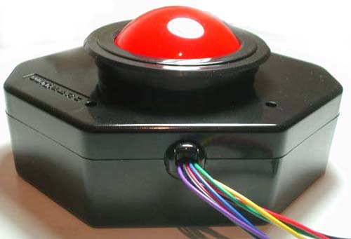
U-Trak
Pearl
Pearl Ball. Shown here with blue LED illumination
Optional Trim Flange |
| |
|
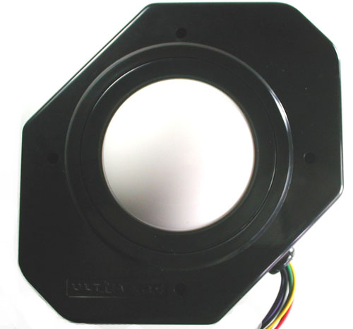 |
U-Trak
CueBall
Top View Cue-Ball White with Trim Flange |
| |
|
 |
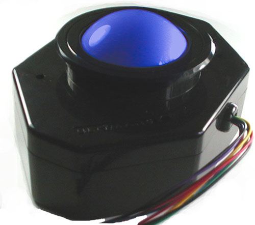
U-Trak
FireBall
Red Ball shown here with Red LED Illumination.
Red self-colored ball gives a rich color when illuminated with a red
LED but still looks great when not lit. |
|
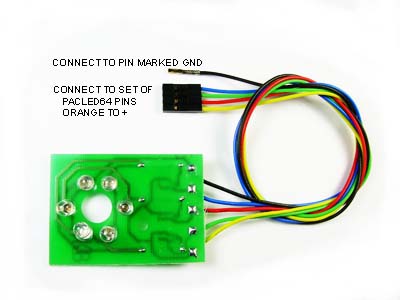
RGB LED Illumination Kit
NEW VERSION with genuine CREE ultra-bright LEDs and MOSFET drivers.
Each pair of Red, Green, Blue high-brightness LEDs has a separate
connection wire. Yellow wire is 5 volts, RGB wires are ground. Can be
connected to a permanent 5 volt supply or plugs directly into our
PacLED64 or Ultimate I/O boards. |
|
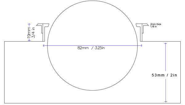
Mounting
Diagram. Shows optional
trim bezel. |
| |
|
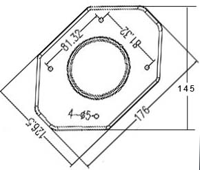 |
Top
view. All dimensions in mm
NOTE Equivalent mounting hole spacing is 3.2 inches. |
| |
|
|
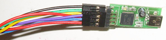
Optional
USB2 interface |
Mounting
Methods
4 Screws and expanding brass inserts are supplied. The inserts are
designed to fit into blind holes and nothing shows from the top of the
panel.
Important note:
Check carefully that the supplied
screws will not pierce through the top of the panel by checking the
length before fitting.
Mounting
without trim bezel:
Using a hole saw or fly-cutter, drill a hole 3 1/4 inch diameter (82mm).
Note the vertical part of the housing is slightly conical to enable it
to be molded in one piece, so to enable a perfect fit you will need to
enlarge the hole from the underside of the panel slightly, using a file.
Fit the trackball with the arrow on the top of the housing pointing to
the rear of the panel.
Drill 4 "blind" pilot holes through the mounting holes. Then remove
trackball and enlarge holes to 1/4 in (6mm). TIP: To drill blind holes
use tape wrapped around drill as a depth guide.
Tap the expanding inserts into place. Install trackball and screw into
place.
Mounting
with trim bezel:
The optimum panel thickness for this method is 5/8 in (17mm). A 3/4
inch panel can be used but the flange will sit 1/8 inch above the ball
surround.
Using a fly-cutter or hole saw cut a hole approx 3 3/8 inch (86mm)
diameter. You may find a 3 1/2 inch or 90mm hole saw is easier to find
and this will work fine.
Fit the trackball with the arrow on the top of the housing pointing to
the rear of the panel.
Drill 4 "blind" pilot holes through the mounting holes. Then remove
trackball and enlarge holes to 1/4 in (6mm).
Tap the expanding inserts into place. Install trackball and screw into
place.
Push the bezel over the housing. Glue can be used if required.
After installation:
You will likely find the ball is quite stiff to rotate in certain
directions. This is owing to the fact it has to slide over
the rollers to some extent and is quite sticky from the manufacturing
process. It will ease with use. For an immediate perfect usage, you can
apply a small amount of liquid soap or hand cream to the ball.
Helpful installation video
here thanks to
Mavericks Arcade.
Connections
(Non-USB)
| Conn A Red |
5 Volts |
| Conn A Black |
GROUND |
| Conn A Purple |
X1 |
| Conn A Blue |
X2 |
| Conn B Red |
5 Volts |
| Conn B Black |
GROUND |
| Conn B Yellow |
Y1 |
| Conn B Green |
Y2 |
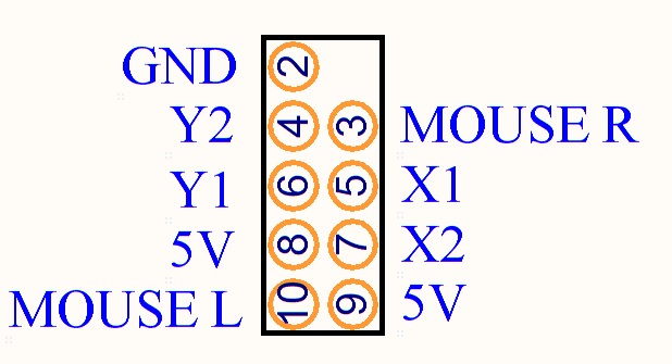
Connections
(USB)
The USB interface supports left and right mouse buttons. Suitable wires
with contacts are contained in the "Mini-PAC Extension harness Pack"
which can be ordered in the Mini-PAC section of our store.
The wires with contacts push into the two unused locations in the black
connector housings.
The COM terminals of the mouse button switches should be connected to a
convenient ground point (Eg an I-PAC ground, or PC casing).
Pinout of USB Interface: